will@jinfengvalve.com
Preparation Before Wiring
Disconnect Power: Before connecting any wires, turn off all power sources.
Consult Product Manual: Different brands of electric ball valves may have varying wiring configurations. Referring to the product manual ensures the safest wiring practice.
Control Wires and Power Wires: Whether using two-wire, three-wire, or five-wire control systems, always distinguish between control wires and power wires.
Step 1: Different Functions of Electric Ball Valves
1. Conventional On/Off Type: This is the most common type of electric ball valve, controlling only the fully open or fully closed position of the valve. It is typically controlled by a 2-wire or 3-wire system.
2. Intelligent Modulating Type: This type allows angle modulation of the valve through the actuator. In addition to power lines, it requires receiving electrical signals to control the angle.
Step 2: Identifying Terminal Connections
Most product manuals include dedicated wiring diagrams. Understand terminal symbols and their meanings.
Common wiring methods:
three wires one wire control Voltage: DC3-6V/DC12V/ADC9-24V/AC85-265V/AC220V
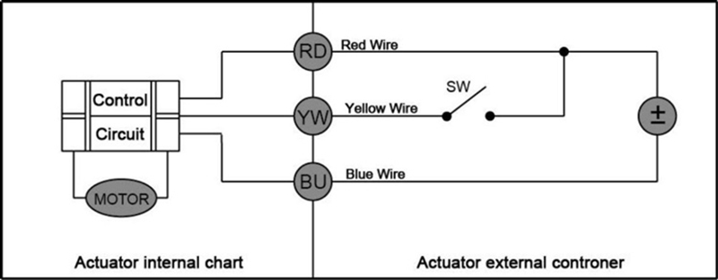
1. Connect the switch to open the motorized valve. When reaching the fully open position, the internal power automatically shuts off, and the valve remains in the open position.
2. Disconnect the switch to close the motorized valve. When reaching the fully closed position, the internal power automatically shuts off, and the valve remains in the closed position.
two wires and fail-safe/power-off return Voltage: DC3-6V/ADC9-24V/AC85-265V/AC220V
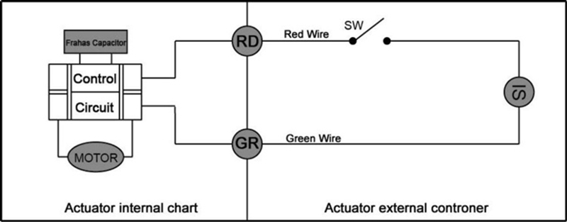
1. When the switch is connected, the actuator rotates clockwise, opening the valve. Upon reaching the fully open position, the internal power automatically shuts off, maintaining the valve in the open state. Simultaneously, the external power source charges the internal backup battery.
2. When the switch is disconnected, the actuator rotates counterclockwise, closing the valve. Upon reaching the fully closed position, the internal power automatically shuts off, maintaining the valve in the closed state.
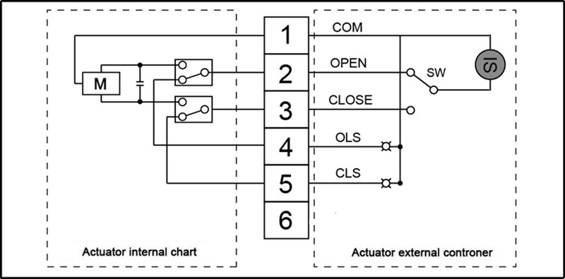
AC passive contact type Voltage:AC220V
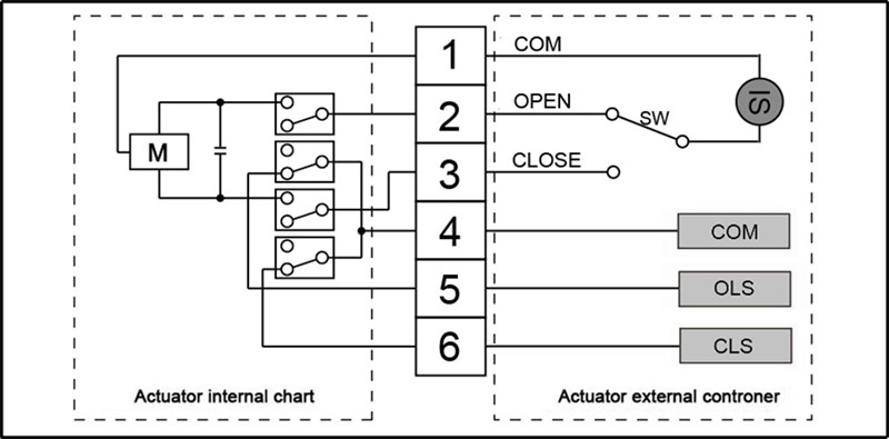
1. When the switch is connected to Terminal 2, the valve opens. Upon reaching the fully open position, internal power automatically cuts off, and Terminal 5 sends a signal feedback, keeping the valve in the open position.
2. When the switch is connected to Terminal 3, the valve closes. Upon reaching the fully closed position, internal power automatically cuts off, and Terminal 6 sends a signal feedback, keeping the valve in the closed position.
AC active contact type Voltage:AC220V
1. When the switch is connected to Terminal 2, the valve opens. Upon reaching the fully open position, internal power automatically cuts off, and Terminal 4 sends a signal feedback, keeping the valve in the open position.
2. When the switch is connected to Terminal 3, the valve closes. Upon reaching the fully closed position, internal power automatically cuts off, and Terminal 5 sends a signal feedback, keeping the valve in the closed position.
Step 3: Begin Wiring
1. Connect the main power supply: Connect the power supply's live wire, neutral wire, and ground wire to their corresponding terminals.
2. Connect the common terminal: Connect one wire from the power supply to the switch's common terminal, and connect another wire to the electric actuator's COM terminal.
3. Connect the switch signals:
Connect the actuator's OPEN terminal to the open contact.
Connect the actuator's CLOSE terminal to the closed contact.
4. Working Principle:
When the switch is connected to the “ON” position, the motor rotates clockwise to open the valve.
When the switch is connected to the “OFF” position, the motor rotates counterclockwise to close the valve.
Final Reminder
Troubleshooting: Before energizing the circuit, manually adjust the valve to the middle position. Then conduct a test to verify the switching direction is correct. If the direction is reversed, simply swap the OPEN and CLOSE wiring connections.
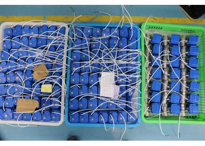
TIANJIN JINFENG VALVE CO., LTD. is a high-tech enterprise specializing in the production of motorized ball valves and motorized butterfly valves.Operating from a 50,000-square-meter facility, the company features dedicated workshops for injection molding, machining, SMT welding, and advanced assembly lines. Backed by a professional R&D team, we hold multiple technical patents. Our products are certified to ISO 9000:2000, CE, RoHS, NSF 61, and other international standards. Through reliable quality and competitive pricing, we have earned a solid reputation among clients worldwide...[ read more ]
![]()
![]()
![]()
![]()
![]()
Contact Person: Will Li
Mobile Phone:+8615122298867
WhatsApp:+8615122298867
E-mail:will@jinfengvalve.com
Add:Taibo South Road, Jinghai Economic Development Zone, Tianjin, Jinghai District